
NORIA FIBER BRAGG MANUFACTURING
Fiber Bragg manufacturing with the NORIA offers both speed and flexibility in writing a large variety of grating types. The fast writing process provides the ability to volume manufacture in-house, while the flexibility of the NORIA enables novel developments in grating designs. This combination will give end-users the advantage of having a powerful development tool, which also provides the ability to initiate production when a grating design is fixed.

Figure 1: NORIA fiber Bragg manufacturing system
INTRODUCTION
Over the past decades, Fiber Bragg Gratings have found numerous applications in various industrial sectors. For example, Fiber Bragg Gratings, or FBG’s for short, are used as high reflective mirrors in fiber lasers to form the cavity and as sensors for down-hole applications to monitor and improve oil production [1, 2, 3], but they are also applied in high speed telecommunication either as selective wavelength filters or as dispersion compensators [4, 5]. With just these few examples and many more to cite it is no surprise that FBG’s are considered a key building block for the Photonics industry.
However, the enormous application potential gives rise to challenges in producing FBG’s as each application demands a different type of grating. Current production sites are optimized to produce vast amounts of gratings, often for one specific application, but lack flexibility. Other sources, often found at universities or research institutes, are optimized for flexibility but lack the capability of reliable production. A solution that combines the best of both worlds has been missing for many years.
NORIA FIBER BRAGG MANUFACTURING SOLUTION
The NORIA (Figure 1) is the world’s first commercially available lithography system for fabricating Fiber Bragg Gratings and offers end-users both speed and flexibility in writing a large variety of grating types. The fast writing process provides the ability to volume manufacture in-house, while the flexibility of the NORIA enables novel developments in grating designs. This combination will give the end-user the advantage of having a powerful development tool in-house, which also provides the ability to initiate production when a design is fixed. The most common method for FBG fabrication is to expose a photosensitive fiber to an interference fringe pattern in UV light. In the NORIA this is accomplished by directing the output of an excimer laser through a phase mask (essentially a diffraction grating). The phase mask diffracts the incident laser light into various orders, which overlap and optically interfere with each other in the mask vicinity. This interference creates stationary, alternating zones of high and low laser intensity, whose spacing is equal to half the phase mask period. Figure 2 provides a schematic overview of the operating principle behind the NORIA.
The excimer laser selected for the NORIA is the Coherent Excistar XS operating at a wavelength of 193 nanometer. The nominal pulse energy of the Excistar is 5 mJ per pulse and delivers 2.5W of illumination power in the UV at a maximum repetition rate of 500 Hz.
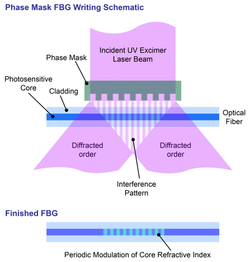
Figure 2: FBG manufacturing using the phase mask method
An energy detector, installed inside the Excistar, measures the pulse energy of each laser pulse, while a fast control loop feeds the laser with high voltage set points. The control algorithm minimizes deviations in pulse energy and ensures a high degree of repeatability in the total accumulated dose when firing a burst. Additional verification of the laser status (e.g. gas condition, pulse energy control) prior to the actual manufacturing is possible by using the external laser shutter.
The optical assembly in the NORIA consists of high grade fused silica lenses and mirrors to efficiently expand, rotate and focus the beam. See Figure 3. The beam is conditioned such that a uniform line focus of 10 mm in length and 20 μm in width at the position of the fiber underneath the phase mask is created. Shorter gratings and/or different illumination profiles (apodized or uniform) are made possible by an aperture slot positioned above the cylindrical lens.
The NORIA supports up to 16 high quality phase masks (Ibsen Photonics) carried on a revolving disc which provides a high level of flexibility and automation. Furthermore, the optical fiber is mounted in a modular fiber fixture which in turn is positioned on a linear stage to reposition the fiber. A novel fiber gripper is used to pick up the fiber and position it with micrometer accuracy and reproducibility in focus of the beam.
The combination of gripper, removable fixture, revolver, illumination optics and excimer laser integrated in the NORIA enables reliable manufacturing of various types of FBG’s in an automated fashion. Figure 3 gives an overview of the separate modules inside the NORIA.

Figure 3: NORIA functional modules
FIBER AND PHASE MASK SELECTION
The NORIA uses high photonic energy from 193 nm radiation, which is reported to give a refractive index change in a wide variety of fiber types, e.g. pure silica fibers [6], rare earth doped fibers [7] and phosphate and fluoride glass fibers [8]. However, optimal performance is reached by using either germanosilicate or hydrogen loaded fibers. An example of a germanoscilicate fiber is the SM1500 series from Fibercore offering a number of fiber types in which the germanium concentration is varied. Note that the photosensitivity of the fiber will increase with the germanium dopant level. However, the germanium will also enlarge the fiber Numerical Aperture (NA), which in turn requires a reduction in core size to maintain singlemode operation. The effect of germanium induced photosensitivity on grating strength (or reflectivity) for 3 different dopant levels is given in Figure 4.
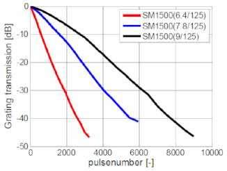
Figure 4: evolution of grating strength while illuminating 3 different germanosilicate fiberss
The single most important FBG parameter for any application is the central wavelength of the grating, dictated by;

In which Neff is the effective refractive index of the fiber and the second symbol the pitch of the phase mask. While the phase mask pitch is selected with an accuracy of ±0.01 nm, the effective index of the fiber is often a bit more tedious to obtain with sufficient accuracy. In addition, variation in the production process of the fiber also gives rise to differences in effective index from batch to batch. The effective refractive index of the fiber can be calculated using the NA provided by the fiber manufacturer. Afterwards a phase mask, whose pitch corresponds to the desired central wavelength, can be selected.
This approach however, does not take into account variations in NA (or effective index) of the fiber.
Therefore, an alternative method in which the fiber is given an accurate pre-strain to fine tune the central wavelength is integrated in the fiber fixture (see Figure 5) of the NORIA.

Figure 5: NORIA fiber fixture with integrated accurate pre-strain feature
Applying a pre-strain to the fiber while manufacturing an FBG will result in a blue shift of the unstrained FBG central wavelength. Due to the unidirectional nature of the compensation mechanism, the effective index calculation and phase mask selection must be based on the
largest possible fiber NA reported by the fiber manufacturer. This approach ensures the NORIA end-user that any variation in NA can be compensated such that the correct FBG central wavelength is manufactured within ±100 pm accuracy. The maximum pre-tension that can be applied to a standard 125 μm fiber is 4 N. The corresponding wavelength shift to 4 N of pre-tension is around 5 nm as indicated in Figure 6.

Figure 6: FBG central wavelength tuning by applying pre-tension to a 125 μm fiber during manufacturing
TUNING FIBER BRAGG PARAMETERS
Next to the FBG central wavelength and reflectivity other parameters of interest (depending on application) are the FBG Full Width Half Maximum (FWHM) and Side Lobe Suppression Ratio (SLSR), see Figure 7.

Figure 7: Fiber Bragg Grating Reflection spectrum indicating SLSR, FWHM and central wavelength
The FHWM or spectral width of the FBG is, in first order, strongly dependent on the physical length of the grating;. Reducing the length will increase the spectral width. The grating length is adjustable by using an aperture plate which blocks part of the beam. The aperture slot is positioned above the focusing lens, see Figure 3. Gratings starting with a maximum length of 10 mm, down to 1 mm are easily fabricated using this method. The corresponding FWHM is given in Figure 8.

Figure 8: FBG spectral width (FWHM) as function of grating length.
Note that both the FWHM and central wavelength are also influenced by the total accumulated dose. For example, when manufacturing a high reflective grating (reflectivity of ~99%) in a Fibercore SM1500(6.4/125) fiber, a red shift of the central Bragg wavelength (caused by the increase in effective refractive index ) in the order of 150 pm is observed while in addition the FWHM increases from 80 pm to around 160 pm, see Figure 9. The effect of illumination dose on the
spectral properties of the FBG needs to be taken into account when fine tuning a specific FBG recipe.

Figure 9: Evolution of grating FWHM and central wavelength red shift as function of accumulated dose. Fiber: SM1500(6.4/125)
For some applications the strength of the side-lobes in the FBG spectrum needs to be suppressed (see parameter SLSR in Figure 7). For example, crosstalk from adjacent channels in a wavelength division multiplexing application must be minimized while simultaneously reducing the separation between optical carriers. The method to reduce the side-lobe strength is by apodization of the grating profile. In the NORIA the illumination profile along the length of the grating can
be adjusted such that both (user-defined) apodization but also uniform profiles are accommodated. Figure 10 depicts the difference between a uniform and apodized grating profile.

Figure 10: schematic example of a uniform and apodized refractive index profile
Switching between the different illumination profiles is a simple matter of changing aperture plates, similar to adjusting the physical grating length. Aperture plates for e.g. Gaussian apodization are defined such that specific parts of the rectangular shaped beam from the excimer laser are blocked. The default illumination profile in the NORIA is a uniform profile dictated by the tophat beam from the Excistar, see Figure 11. Note that the cylindrical lens underneath the aperture slot position condenses the width of the beam to a line width of around 20 μm, while the length remains unaltered (length and width as indicated in Figure 11).

Figure 11: laser beam profile measured at the position of the aperture
slot and cross sections
With the beam profile and an apodization profile design (e.g. Gaussian) as input, the aperture plate dimensions can be calculated in a straightforward manner. An algorithm selectively removes parts of the beam and compares the result after summation along the width of the beam to the desired illumination profile. An example of this process is given in Figure 12, in which the aperture shape for a Gaussian illumination profile (sigma = 2 mm) is calculated.

Figure 12: a.) original tophat and desired Gaussian illumination profile. b.) calculated aperture shape (blue blocks the beam) c.) resulting illumination profile.
The aperture presented in Figure 12 (b.) used in the NORIA results in an FBG reflection spectrum as presented in Figure 13. For comparison the spectrum of a uniform illuminated FBG is added.
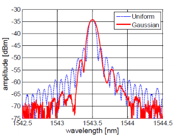
Figure 13: FBG reflection spectra of Gaussian apodized grating and a uniform grating.
Note that the SLSR increases from around 10 dB using a uniform illumination to around 18 dB suppression with the designed Gaussian illumination profile.
CONCLUSION AND OUTLOOK
The NORIA offers the flexibility to adjust many different grating parameters which is often required e.g. when designing a novel sensor or optimizing the grating design in a fiber laser cavity. Parameters like the central wavelength, FWHM, SLSR and reflectivity can easily be tuned and optimized with little time and/or effort from the end-user. Furthermore, when a grating design for a specific application is sufficiently evolved the NORIA is capable of producing large amounts of gratings of this design in an unprecedented reproducible manner.
With these capabilities, the NORIA is expected to lower the entry barrier for Photonics related SME’s to develop and manufacture FBG’s. In the future significant technological innovations in which FBG’s are used are therefore expected. For example, FBG’s have been acknowledged as key component for minimal invasive medical procedures allowing precise and accurate point, multipoint, or distributed measurements, while overcoming limitations of conventional techniques [9]. With the introduction of the NORIA such sensors will be developed faster and more cost effective, giving rise to reduced cost in medical procedures.
REFERENCES
1. Waleed Mohammed and Xijia Gu, "Fiber Bragg grating in large-mode-area fiber for high power fiber laser applications," Appl. Opt. 49, 5297-5301 (2010).
2. Mathieu Faucher, Eric Villeneuve, Benoit Sevigny, Alexandre Wetter, Roger Perreault, Yannick Keith Lizé, Nigel Holehouse, “High power monolithically integrated all-fiber laser design using single-chip multimode pumps for high reliability operation,” Proc. SPIE 6873, Fiber Lasers V: Technology, Systems, and Applications (February 22, 2008)
3. L.K. Cheng, W. Schiferli, R.A. Nieuwland, A. Franzen, J.J. den Boer, T.H. Jansen, “Development of a FBG vortex flow sensor for high-temperature applications,: Proc. SPIE 7753, 21st International Conference on Optical Fiber Sensors (May 17, 2011)
4. R. Romero, O. Frazao, F. Floreani, L. Zhang, P.V.S. Marques, H.M. Salgado, “Chirped fibre Bragg grating based multiplexer and demultiplexer for DWDM applications,” Optics and Lasers in Engineering 43 (2005)
5. Petruzzi, P., Lowry, C., Sivanesan, P., “Dispersion compensation using only fiber Bragg gratings”, IEEE Journal of Selected Topics in Quantum Electronics, Vol. 5 , Iss. 5, Sep/Oct 1999.
6. Albert J., Fokine M., Margulis W. Grating formation in pure silica-core fibers. Opt. Lett. 2002;27:809–8111
7. Lingyun Xiong, Peter Hofmann, Axel Schülzgen, N. Peyghambarian, and Jacques Albert, "Photosensitivity and thermal stability of UV-induced fiber Bragg gratings in phosphate glass fibers," Opt. Mater. Express 4, 1427-1435 (2014)
8. J. Canning, M. G. Sceats, H. G. Inglis, P. Hill, “Transient and permanent gratings in phosphosilicate optical fibers produced by the flash condensation technique,” Opt. Lett., 20, 2189-2191 (1995)
9. Paulo Roriz et al, “Review of fiber-optic pressure sensors for biomedical and biomechanical applications”, Journal of Biomedical Optics 18(5), (May 2013)